CALCULATION PROBLEM IN INDUSTRY HEAT EXCHANGER
Heat Exchanger Analysis Heat Exchanger Calculation. The basic design calculation for any heat exchanger is the determination of heat transfer area.

Surface Condenser Difference Between Jet And Surface Condenser Thermal Power Plant Condensation Surface
Shell and Tube Heat Exchangers.

. A heat transfer area in m2. The rating program is shown schematically in Figure 41. The overall heat transfer coefficient U 200 Wm 2 K.
These templates use SI. 124 Heat transfer in single-phase flow Heat transfer in helical coils has been experimentally investigated by Seban McLaughlin 1963 both for laminar and turbulent flow regime s for flow of water with constant wall flux BC. Download the Excel spreadsheet templates in this article to make preliminary heat exchanger design calculations.
Ribbed tube heat exchangers make the use of internal ribs 1. Fourier Law for conduction will help in heat calculation through a flat plate. Ad Designed and engineered for quality.
Shell - and - Tube Design Contd Download To be verified. The log-mean temperature difference method LMTD provides a rate of heat transfer through the following calculation. Overall heat transfer in any exchanger is governed by the following equation - Equation-1.
Design and Development of Spiral Tube Heat Exchanger Ajay S Hundiwale1 3Samuel Raju2 Saikrishnan Ramesh. T 1 Inlet tube side fluid temperature. The specific heat of the oil is 22 kJkg K.
In the analysis of heat exchangers it is often convenient to work with an overall heat transfer coefficient known as a U-factorThe U-factor is defined by an expression analogous to. Enhancement of Heat Transfer compact. The simplest heat exchanger is one for which the hot and cold fluids move in the same or opposite directions in a concentric tube or double-pipe construction.
H for plate heat exchanger is often in between 2 to 7 kWm 2 K -1. Check sum of heater duties 800 1250 850 2900 kW hot utility target. Browse SRC industrial heat exchanger products.
ΔT m T 1 t 2 T 2 t 1 F Where. 40 HEAT EXCHANGERS CALCULATIONS. Δ Hhot 1600 750 850 kW.
The heat load of a heat exchanger can be derived from the following two formulas. Equation 1313 is used when simple counter or co-current flows exist. Then the basic design equation becomes.
Heat exchangers are commonly used in industry and proper design of a heat exchanger depends on many variables. The problem is to design a suitable spiral heat exchange system for liquid to liquid heat transfer and use this heat for a particular process industry. Our aim is to design a.
In addition the overall heat transfer equation for the exchanger must be solved simultaneously. Calculate the required heat transfer area based on values needed. When the overall heat transfer coefficient is constant and the other assumptions of the mean temperature difference concept apply.
Heat exchangers are commonly used in industry and proper design of a heat exchanger depends on many variables. Most generally this is done using although in practice it is more common to assume that fluid properties can be treated as constant at the bulk average values and approximate the design equation with. A heat exchanger is a piece of equipment built for efficient heat transfer from one medium to another.
The critical issue when designing the heat exchanger is the determining of the thermal exchange coefficients reliably and accurately. Heat Exchanger Analysis Heat Exchanger Calculation. Heat transfer through conduction is directly proportional to the area of heat transfer and corresponding temperature gradient.
Heat load Theta and LMTD calculation. Learn how from the experts at SRC. Include a heater on the smaller branch of stream 3 to provide the balance of the heat required.
2 The sizing problem however is concerned with the determination of the dimensions of the heat exchanger. Determine the area of this heat exchanger required for this performance. Our heat exchangers help your system work smarter.
In ordinary heat exchanger there is simple tubes are used. Design and Simulation of Heat Exchangers - Numerical Problem Contd Download. 13 with being the overall heat transfer coefficient the heat transfer area and is the log-mean temperature difference.
Design and Simulation of Heat Exchangers - Numerical Problem Contd Download. T 2 Outlet shell side fluid temperature. In the analysis of heat exchangers it is often convenient to work with an overall heat transfer coefficient known as a U-factorThe U-factor is defined by an expression analogous to Newtons law of cooling.
Q kAΔTX Where k thermal conductivity of the material in WmK. In the sizing problem. The main basic Heat Exchanger equation is.
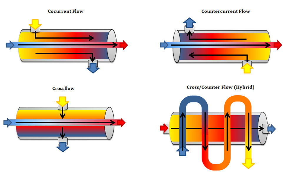
In the parallel-flow arrangement of Figure 188a the hot and cold fluids enter at the same end flow in the same direction and leave at the same end. Include a heater on stream 4 to provide the balance of the heat required. Q UAFΔTlm In this equation U is the overall heat transfer coefficient A is the total area of heat transfer ΔTlm is the log-mean temperature difference and F is the log-mean temperature difference correction factor.
Roger Mayhew 1964 studied heat transfer to fluid flowing inside a helical pipe which was heated by steam. Temperatures and the pressure drop for an existing heat exchanger. ΔHhot 20 100 750 1250 kW.
QT U AFLMTD 21 where QT is the total heat load to be transferred U is the overall heat transfer coefficient referred to the area A A is any convenient heat transfer area LMTD is the. Often LMTD counter flow LMTD parallel flow. P heat load btuh m mass flow rate lbh c p specific heat btulb F δt temperature difference between inlet and outlet on one side F k heat transfer coefficient btuft 2 h F A heat transfer area ft 2.
Q U x A x ΔT m The log mean temperature difference ΔTm is. Therefore the heat transfer surface area and the flow passage dimensions are available. The rate of flow of oil is 1 kgs.
Calculate the logarithmic mean temperature difference. Where Q overall heat transfer rate U Overall heat transfer coefficient A Overall Overall heat transfer surface ares LMTD Logarithmic Mean Temperature Difference. The basic selection done are 1.
Tubular Heat Exchanger. H overall heat exchange coefficient kWm 2 K-1 S area of the heat exchanger m 2 ΔT ml K The value of S can thus be calculated as a 1st approximation of the heat exchanger size. The selection of temperatures by survey or.
The logarithmic mean temperature difference can be calculated simply using its definition. They will also calculate the number of tubes needed for a shell and tube heat exchanger and to calculate the pipe length needed for a. A wrong calculation will result in a lack of performance and the heat exchanger may even not reach the required temperatures.
When there is insufficient information to calculate the log-mean temperature difference LMTD the so-called number of transfer units NTU method is used to calculate the rate of heat transfer in heat exchangers especially countercurrent exchangers.

Calculating Heat Loss 2016 12 01 Process Heating

Heat Exchanger Approach Temperature Enggcyclopedia

Plate Heat Exchanger Applications And Working Principle Hvac Heat Transfer Youtube

Heat Transfer Coefficient Of Liquid Liquid Tubular Heater Calculation Htc Heat Transfer Tubular Heater Heat

Heat Exchanger Design An Overview Sciencedirect Topics

Shell Tube Heat Exchanger Enggcyclopedia
Understanding Heat Exchangers Types Designs Applications And Selection Guide

Steam Consumption Of Heat Exchangers Spirax Sarco
Shell And Tube Multipass Heat Exchanger Design Tubular Juice Heater Heat Exchanger Heater Vacuum Filter
Belum ada Komentar untuk "CALCULATION PROBLEM IN INDUSTRY HEAT EXCHANGER"
Posting Komentar